The layout for the Control Circuit is based on Hugh Piggott\'s design which he kindly did for me. This shows the 48V AC produced by the Turbine being rectified into DC and then two LDR 48-30 Controllers control the load on the turbine. Initially I have just one LDR and one Immersion Heater, but now have two 1kW 48V DC Immersion Heaters, one in the Hot Water Tank (also heated by solar panels) and the other in the under floor heating buffer tank.
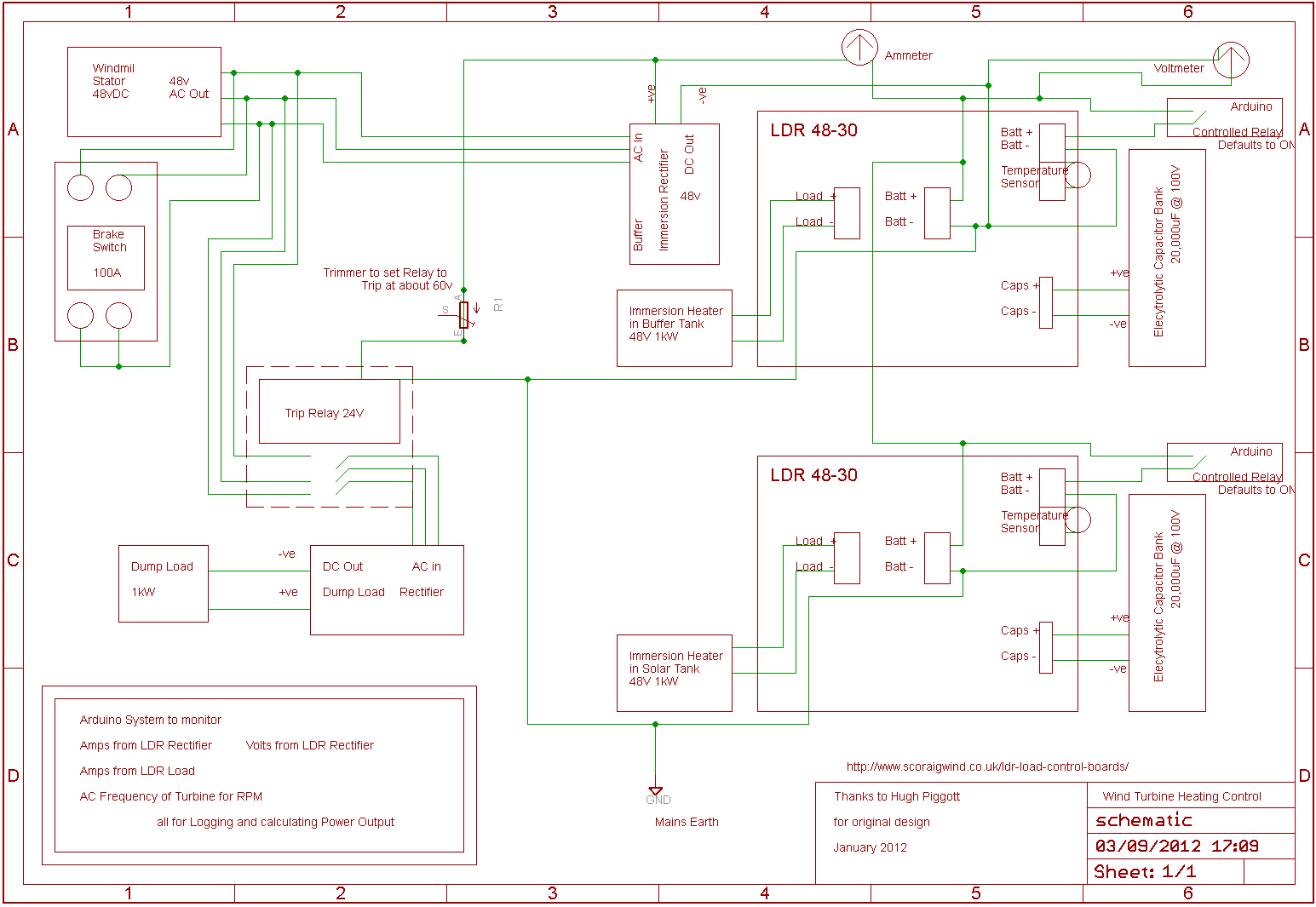
I bought the controllers from Hugh. He has a good page on his site explaning this system. The LDRSs are controlled by relays (default ON to both tanks) switched by my Arduino Control System. If the voltage from the turbine exceeds a level set by a trimmer, then the Trip Relay diverts into a 1kW Dump Load for safety.
I have used an Arduino Mega with an Ethernet Shield to monitor the output with a support program in Java to display the data on my computer at home. The data is uploaded to this site every few minutes and can be seen here.
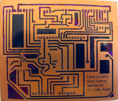
I made a Custom Shield for the sensor circuits which consist of measuring Frequency of AC to calculate the RPM, Amps and Volts going into the Controller and both Immersion Heaters. From this the power can be calculated and graphed
The Arduino monitors through a mixture of Analogue and Digital Pins. Some pins are reserved for the Ethernet Shield. I also have a DS1307 Clock to keep time, using NTP to set accurate time on startup.

From the top:
- A Voltage Divider to allow volts to be measured on pin A0
- AC Frequency using an optocoupler and interrupt on pin D2
- DS1307 RTC Clock on pins A4 and A5
- Liquid Crystal Display using a Shift Register uses pins D7, D8, D9
- Buffer Amps and Solar Amps use pins A1, A2
- Solar Tank Temperature A15
- LDR Relay contorl from D31 and D33
- Power Supply using LM 317 to convert 12V to 9V to drive Arduino
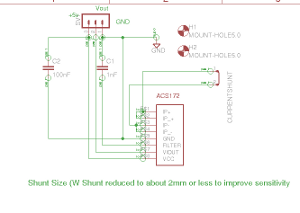
For Current Sensing I used Allegro Hall Effect Sensor chips the ACS172 for 20A and ACS758 for 50A going into pins A1 and A2. The ACS172 layout was modified as per this article to increase sensitivity to cope with 50A output
Here is the Control Box with everything packed in.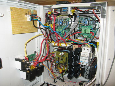
- Top Left on the open door are the LDR relays and LED Indicators
- Bottom Left on the door are the LCD screen and analogue Volt and Ammeters
- LDR 48-30 Controllers are the green boards with the trip relay above them
- 2 banks of Capacitors (Black) below the LDR 48-30s
- Arduino is hidden beneath my Custom Shield bottom left
- The Amp Sensors are seen edge on between LDRs and Arduino
- Middle Right is the 100A Brake Switch
- Bottom Right is the 12 v PSU to drive the Arduino
- Two 12v computer fans at the top to ventilate the case running at 5v
The Rectifiers are not in here but adjacent behind a big heat sink. And the Dump Load is further off on the wall